Ysterhout Dot Net
This is how the ejector in the video looks up close. You can see that the leading edge of the ejector is mostly fine, there is just a small section near the middle that seems to be wearing, and that is where the case rim is riding up the ejector instead of being pushed along the face to eject.
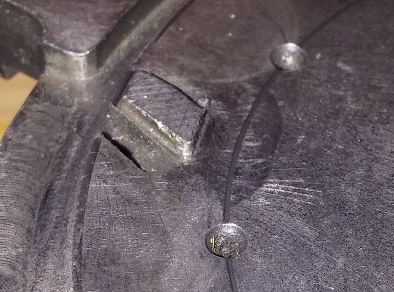
Once the ejector starts to wear, there is no adjustment you can make to any other part to get it working, you have to either re-create it or get a new sub-plate.
The fix is dramatic, but effective. A weld bead deposited on the ejector, then it is ground back to shape with a dremel.
I have fixed both my presses this way, and they now cycle flawlessly.
As I mentioned, Hornady would have shipped me a new sub-plate if I had contacted their warranty department, but time was a factor for me to get the press working again.
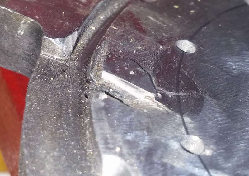
The ejector on the Hornady Lock-n-Load is a weak point in the design of the press, and can easily be improved by Hornady.
The ejector needs to be made as a removable part held in place with a tapered head screw. The ejector can be 1mm thick [ not 0.7mm ] and of a harder steel than the sub-plate. As a replaceable part, Hornady could save a lot of money by not having to replace the entire sub-plate whenever the ejector gives problems under warranty.
Note that if the shellplate is not tight on the drive hub, the clearance between the shellplate and the ejector allows the case rim to slip between the shellplate and the ejector, causing a bind.
It takes very little apparent wear on the ejector to render it faulty.
I will proceed to illustrate how a cumulative variation in parts tolerance can contribute to the ejector becoming worn initially.
I have 2 presses, one was pre-Ezject and got the Ez-ject upgrade, the other was purchased with the Ez-ject system.
The underside of each sub-plate appears different, but the difference is cosmetic as the critical dimensions are almost identical.
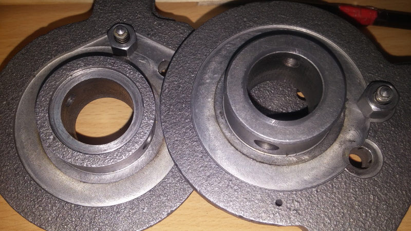
Note that on the right sub-plate, there is a more prominent groove worn into it where the lip of the drive hub rotates against the bottom of the sub-plate. This further increases the part tolerance difference.
There is a difference of 0.66 mm in critical dimension between the sub-plates.
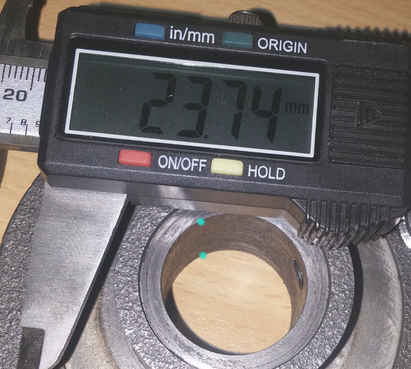
23.74 mm
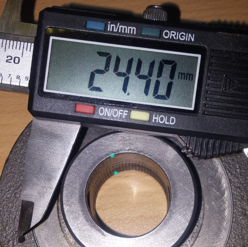
24.40 mm
This means that if the drive hubs were identical, one sub-plate would allow the drive hub [ and hence the attached shellplate ] 0.66mm higher over the sub-plate [ and the ejector ] than the other. The ejector is only 0.7mm high, and gives a 0.5mm clearence between the shellplate and the ejector. With this 0.66mm dimension variation, the possible gap becomes 1.16mm, so increasing the probability of the case rim riding over the ejector, causing the initial wear, and over time rendering the ejector ineffective.
Note the wear on the bottom of the sub-plate by the lip of the drive hub. This potentially adds to the critical dimension variation. Both drive hubs show degrees of wear at that contact point, and is expected where metal parts move in contact with each other.
If the ejector was replaceable, and made to 1.0mm, this wear would not be a factor in shellplate clearance of the sub-plate.
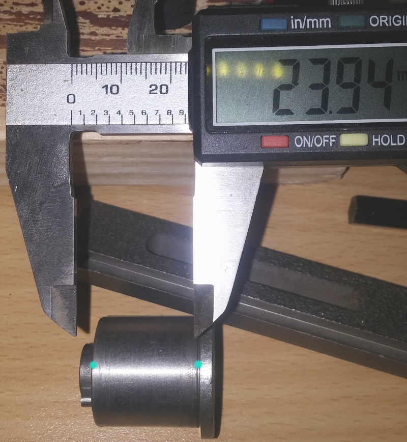
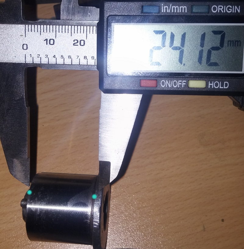
The variation of the critical dimension on these drive hubs is 0.18 mm. This 0.18 added to the possible 1.16mm brings the overall to 1.34mm, which is nearly double the 0.7mm height of the original ejector. Because the shellplate is flush against the drive hub, it cannot be tightened further, and the gap between the shellplate and the ejector can not be reduced.
This is how a drive hub fits normally to a drive shaft. There is a degree of movement in the vertical.
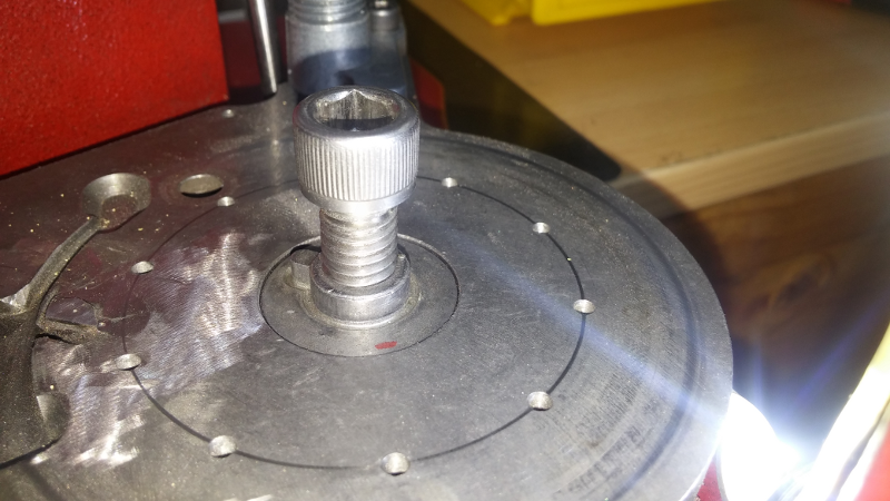
Tightening the hex bolt with a shellplate fitted moves the drive hub slightly above the level of the sub-plate. That small difference is the clearence available to the shellplate when rotating over the sub-plate.
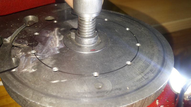
The drive hub must be able to move vertically freely on the drive shaft, because if it is stuck to the drive shaft and remains below the shellplate, like the picture below, when you fit the shellplate and tighten the hex bolt, the shellplate binds to the sub-plate and does not rotate.

Initially, I thought that the drive hub had shifted up off the drive shaft causing the problem. After looking at the problem more carefully, I realised that the vertical position of the drive hub on the drive shaft had nothing to do with the problem, as the lip of the drive hub could not pass the bottom of the sub-plate, so it is not possible for the drive hub to move above the shellplate any variable amount.
Instead, the difference in height between the top of the drive hub and the sub-plate is the sum of the dimensional tolerances of the critical dimensions.


